
You are using an out of date browser. It may not display this or other websites correctly.
You should upgrade or use an alternative browser.
You should upgrade or use an alternative browser.
Need help setting up drone
- Thread starter Marijn
- Start date
I think I already know why I have 2 vtx's connected. Before this drone I had another drone. Sadly, I crashed this drone in the water. When my previous drone crashed, the vtx was not on it so I had a spare one. I think I just connected this thing to my drone a year ago and was hoping a miracle would happen.


Remember what I said about "guessing"? Hopefully nothing is broken and it will start passing testing and setup now.I think I just connected this thing to my drone a year ago and was hoping a miracle would happen.
So, I also have a question not related to the FC and ESC. I now have the charson dc-4s for charging, but this thing is very bad. I can use it to check the voltage of the battery, but when I plug the battery and the power supply in, it gives a error code. (Error code 4). So now I can't charge my batteries.
Could you recommend me a good charger for my 4-cells batteries? Also, my budget is very low because I'm a college student and don't have a lot of money a the moment.
Could you recommend me a good charger for my 4-cells batteries? Also, my budget is very low because I'm a college student and don't have a lot of money a the moment.

I already know the problem I think, I need a adapter with an output of 1500 mA. The adapter, which I'm using now has an output of 1500 mA
There is a lot to know about the LiPo batteries we use in these things, in all likelihood the battery has 1 or more cells that have dropped below about 3 volts, at that time it knows the battery is dangerous to charge and will not start a charge cycle. Ideally you have a voltmeter or a separate battery checker to see what your individual cell voltages are at the balance lead and can possibly recover it if it isn't too low. Do you have access to (and know how to use) a voltage meter (multi meter) to check this battery? I doubt the charger is bad.
I'm not sure you are looking at this right, I am guessing you don't have a lot of electrical or electronic background, the plug in power supply is all about the rated voltage and current output, as long as the voltage out falls into the voltage in range on the charsoon, it should work.
So I have a third and (hopefully) last problem with my quadcopter, my vtx isn't working. I have the 5.8G 72CH 25MW 200mw 600MW switchable transmitter and it is connected to the FC as you can see in the pictures.
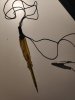
Here is a picture of the VTX:

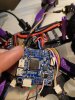
And the connection to the FC:

The VTX is connected to these pins on the FC:

When I power up my quad, nothing happens on the VTX. No lights and the display that should show the channel are lighting up. Also, when I go to the video tab in BF, I says the VTX is not connected.
On the VTX something looks a bit melted, but maybe it's supposed to look like that. Take a look at this:

Also the camera was connected to these three pins:

However, these cables came loose. Do you think I can just solder them back on or is this hard to do. (I'm not very good at soldering).
Here is a picture of the VTX:
And the connection to the FC:
The VTX is connected to these pins on the FC:
When I power up my quad, nothing happens on the VTX. No lights and the display that should show the channel are lighting up. Also, when I go to the video tab in BF, I says the VTX is not connected.
On the VTX something looks a bit melted, but maybe it's supposed to look like that. Take a look at this:
Also the camera was connected to these three pins:
However, these cables came loose. Do you think I can just solder them back on or is this hard to do. (I'm not very good at soldering).
Looking at the diagram below, the RAM pad on J3 should be shorted (with a short wire or a solder bridge) to either VBAT OR 5V and that will decide if full battery voltage or 5 volts is applied to the other pads labeled RAM up where your camera and vTX are attached. I am assuming it came from the factory shorted to the appropriate place for what came with your quad. I can't really guess what might be wrong here, you should check the RAM pad to the GND pad next to it to see what voltage is present to be sure. Look to see where the pad is shorted according to this.

There is nothing melted there except solder, and that is what it is supposed to look like so I don't see any real issue from what I can tell. It is very important to know what the input voltage range is on the cam and vTX to be sure that it has enough voltage but not too much voltage, but again, I assume it came properly from the Eachine factory. And of course any broken wires can be re-soldered on.
I am tagging @Futuramille to see if he can post the soldering video he has and maybe that will help you get the cam wires re-soldered on.
It looks like it is shorted so that the cam and vTX pads get full battery voltage. I would check it with a meter to make sure that the voltage is there when the battery is plugged in and check at the vTX connector that the voltage is getting there.
I don't think that will work, it will not tell you what the voltage is and it may not work with anything other than 6v/12v automotive circuits. There are many very inexpensive meters out there and you really need one to be in this hobby. Here is an example that will work and is extremely inexpensive.

 www.harborfreight.com
7-Function Digital Multimeter
Amazing deals on this 7 Function Digital Multimeter at Harbor Freight. Quality tools & low prices.
www.harborfreight.com

It really isn't that hard, but you need to be really careful not to short the pins with just one lead of the meter. You can also unplug the connector and check on the retaining clip for the sockets in the connector.

I would think it was something along the lines of...
vTX is blown up
Wire could be broken
VBAT may not actually be available at the pads like it should
vTX was actually a 5v model instead of one that can accept VBAT so it got blown by over-voltage, and the same for the camera, but I would guess that is not it because it came from the factory like that?
Bottom line is it is not getting power and ground, or it is damaged.
Ok, so I managed to test the voltage with a multi meter.

I tested the power between the two red circles, and the voltage meter stayed at 0. To test the voltage meter, I measured the voltage between the two blue circles and I got a voltage of 0.
Then I saw a cable from the ESC to the FC came loose.

You can see here where they are connected to the FC

This is how the red and the black cable are connected to the ESC:

Is this the problem or doesn't this loose cable really matter? So the more I think about it, I must be the problem. Because otherwise, the FC doesn't have a power supply. So I should just solder the black wire back on right?
I tested the power between the two red circles, and the voltage meter stayed at 0. To test the voltage meter, I measured the voltage between the two blue circles and I got a voltage of 0.
Then I saw a cable from the ESC to the FC came loose.
You can see here where they are connected to the FC
This is how the red and the black cable are connected to the ESC:
Is this the problem or doesn't this loose cable really matter? So the more I think about it, I must be the problem. Because otherwise, the FC doesn't have a power supply. So I should just solder the black wire back on right?
Similar threads
- Replies
- 0
- Views
- 899
- Replies
- 0
- Views
- 791
- Replies
- 1
- Views
- 655
- Replies
- 2
- Views
- 1K